Unified Modeling Language is the meaning in Spanish for these acronyms. Through UML it is possible establish the requirements and structures necessary to establish a software system prior to the process long code writing.
In other words, just as an architect needs plans for the building he is going to build, the work team needs UML diagrams that dictate the topics of the software to be developed, which encourage the members participate and communicate easily, ranging from analysts, designers, area specialists and of course the programmers.
Since UML is used in medium-high complexity systems, it is expected that high-level languages will be used and of course object-oriented programming, so working in UML can be considered a prerequisite, have experience in an object-oriented language, have complex development and of course develop according to software architecture standards.
Concepts / Diagrams
Among the fundamental concepts of object orientation are the following:
- A model is an abstraction of the problem being attempted
solve.
- A domain is the world where the problem comes from.
- A model consists of objects that interact with each other
sending messages.
- Each object has its own characteristics (attributes) and operations that
can perform (methods); The values assigned to an object at a given time determine its
state.
- A class is a template for describing an object that groups
characteristics (attributes) and behaviors (methods).
- Objects are instances of Classes.
Listed below are the 8 diagrams that form the basis of UML, and dictate how it is designed a system:
|
|
Use Cases
The use case diagram represents the
how a Client (Actor) operates with the system under development, in addition to the form, type and order in which
the elements interact (operations or use cases).

Class Diagram
It is a type of structure diagram
static that describes the structure of a system showing the system classes, their attributes,
operations (or methods), and the relationships between objects.

Object Diagram
It is a type of diagram that shows a
complete or partial view of the objects of a system at a specific execution time.

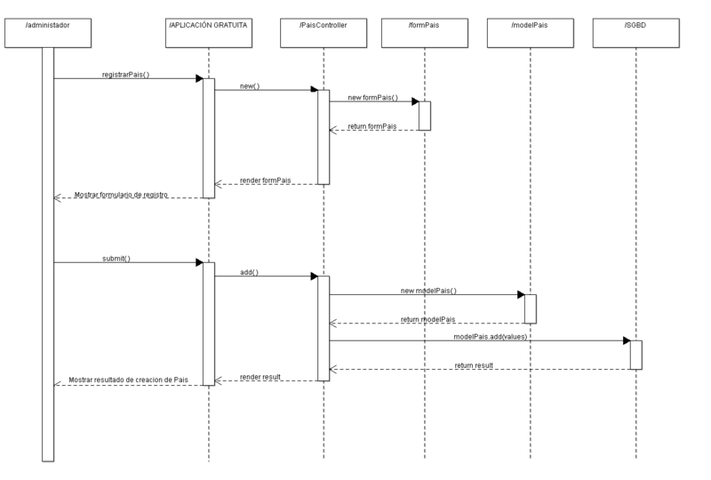
Sequence Diagram
The sequence diagram
Sequenceis a type of diagram used to model interaction between objects.
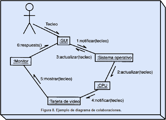
Collaboration Diagram
A collaboration diagram
Collaborationis essentially a diagram that shows interactions organized around the
roles. Unlike sequence diagrams, collaboration diagrams, also called
Communication diagrams explicitly show role relationships.
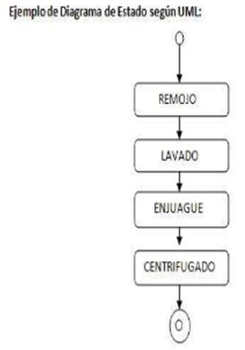
State Diagram
State diagrams show the
set of states through which an object passes during its life in an application in response to events.
Ex. State diagram of a washing machine.
Activity Diagram (The famous activity diagram!
flow!)
The flow chart or activity diagram is the graphic representation of the
algorithm or process.

Component diagram
A component diagram, such as
A software system is divided into components and shows the dependencies between them. The components
Physical assets include files, headers, shared libraries, modules, executables, or packages.
The topic is vast and each of these diagrams has its rules, I invite you to learn more about UML in this Wiki which is dedicated to the topic.
https://wikiuml.wikispaces.com/
Personally,
I consider that these diagrams are necessary for professional and well-documented software, since in a
future, if someone else takes up the project that we worked on, with these diagrams they will understand it clearly.
faster and thus, a faster software development process will take place.
controlled.